Caprile Observatory
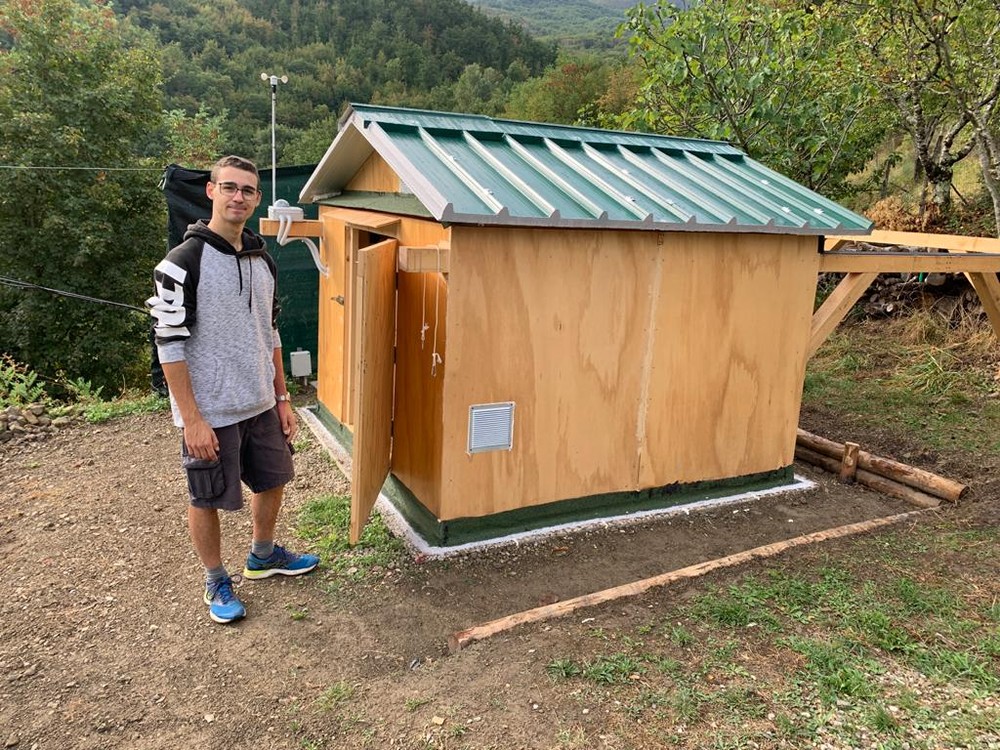
After my final high school exam, a friend of mine asked me if I was available for what turned out to be my greatest project: building an astronomical observatory in the Florence’s countryside. Ambitious, hard, but here I am telling you about it! First of all, I am sorry if I will not provide exact instructions on how to build it: as you can imagine, there are so many parts in this observatory that it would take me a year just to describe everything. However, if you want to make your own, I invite you to thinker and come up with your unique solutions to the problems you will certainly face: by doing so, you will certainly learn a lot and enjoy more the journey!
Sponsor

Thanks to DigitSpace for sponsoring this project! They contributed to the making of the electronics by providing sensors, cameras and other components! More about them in the section about the electronics.
Photos
The aim of the project
My friend wanted a fully remote observatory for his astrophotography setup, possibly on a budget and as reliable as possible. Unfortunately, pre-made sliding structures are really expensive, usually made of metal (so hard to dismantle and recycle) and lack the kind of remote control he wanted. There are also remote control systems, but they are usually professional and complex. That said, the aim of this project was to find a custom solution to all these problems while being a great opportunity of learning and making experience.
The plan
Every big project must have one: in this case, there were a lot a constrains and requirements that needed to be fulfilled:
- The roof must slide completely and the structure must not hide parts of the sky
- No cement foundations, since the observatory would be located in a front yard and not in building plot
- Must withstand the snow and heavy rain typical of that place
- Must not require special machines to build or extraordinary transports for the material
- Stay within a budget of €3000, labor and astronomical equipment excluded
- Must be fully remote, have a web interface to open/close the roof and monitor everything
- Must be able to turn on and off the equipment, the telescope’s PC and the AC plugs
- Security cameras and PIR alarm, with notifications and recording
- Weather station, all-sky camera and anemometer
Moreover, add to this list the countless dimension limits and the sleepless nights spent defining every single detail before start the actual design! Bear in mind that this is a simplified list of the fundamental requirements: the accurate planning of the observatory took an entire month of full-time work for both me and my friend. We had to research and study a lot about how to build wood structure, think about the sliding roof, look for the best suited electronic components and so on.
Designing the structure
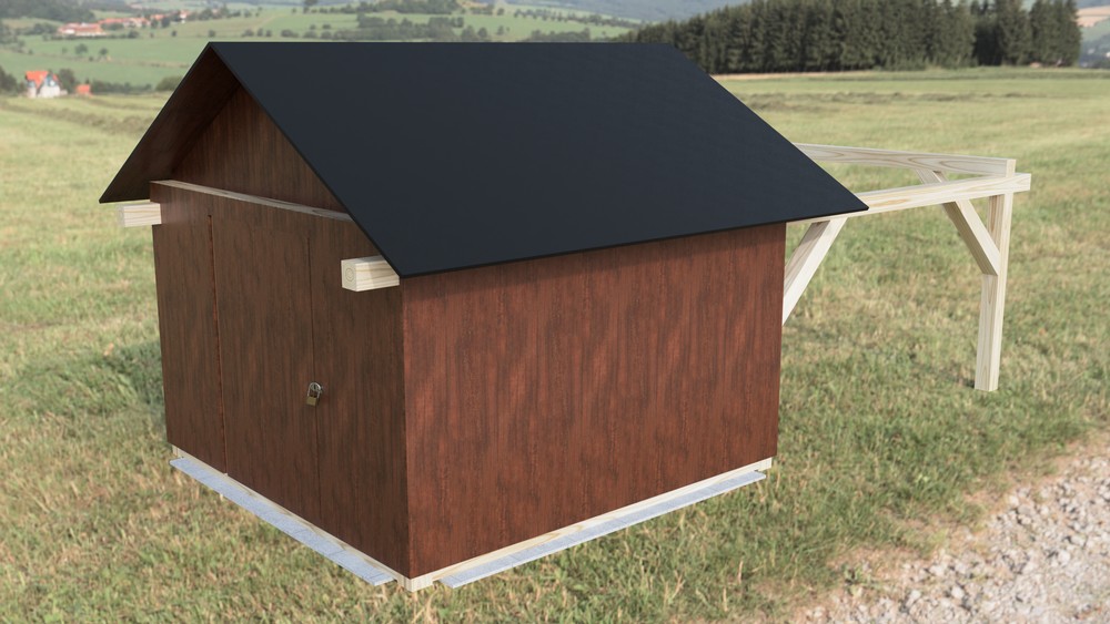
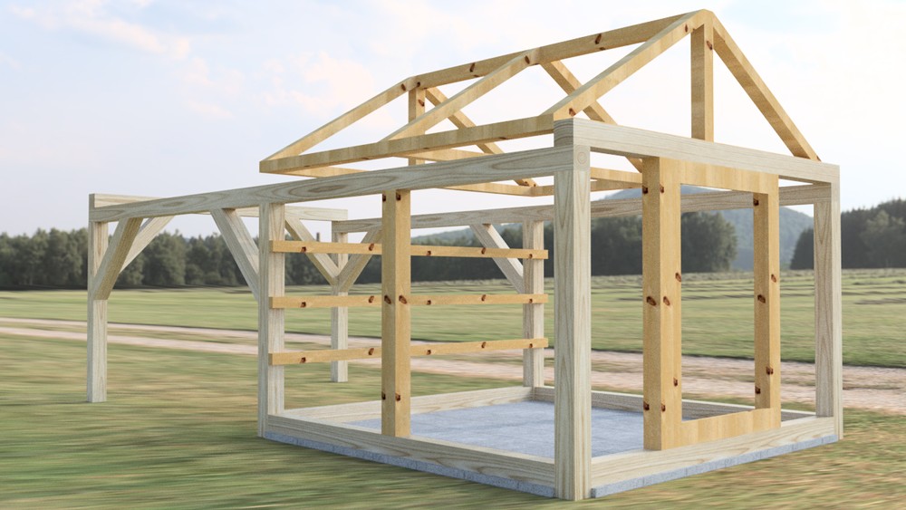
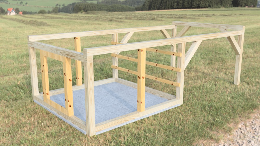
This was no easy task: I had to draw every single part of the observatory using Fusion 360 for a number of reasons: I needed to check each dimension, get a sense of how the structure would be, simulate the movements of the telescope (i.e. use motion studies to point the telescope and see if the walls block the view) and finally create a sort of instruction manual for my friend to buy, cut and assemble the wood. Indeed, due the 2020 pandemic and the fact that I live in Rome, away from the place where it would have been built, my friend built the structure on his own following my design, while I worked on the electronics at home.
I will not be providing the exact instructions and dimensions, since they are labelled in Italian and would be above all pointless without an exact explanation of each part. Here are, however, some of renderings I’ve done:
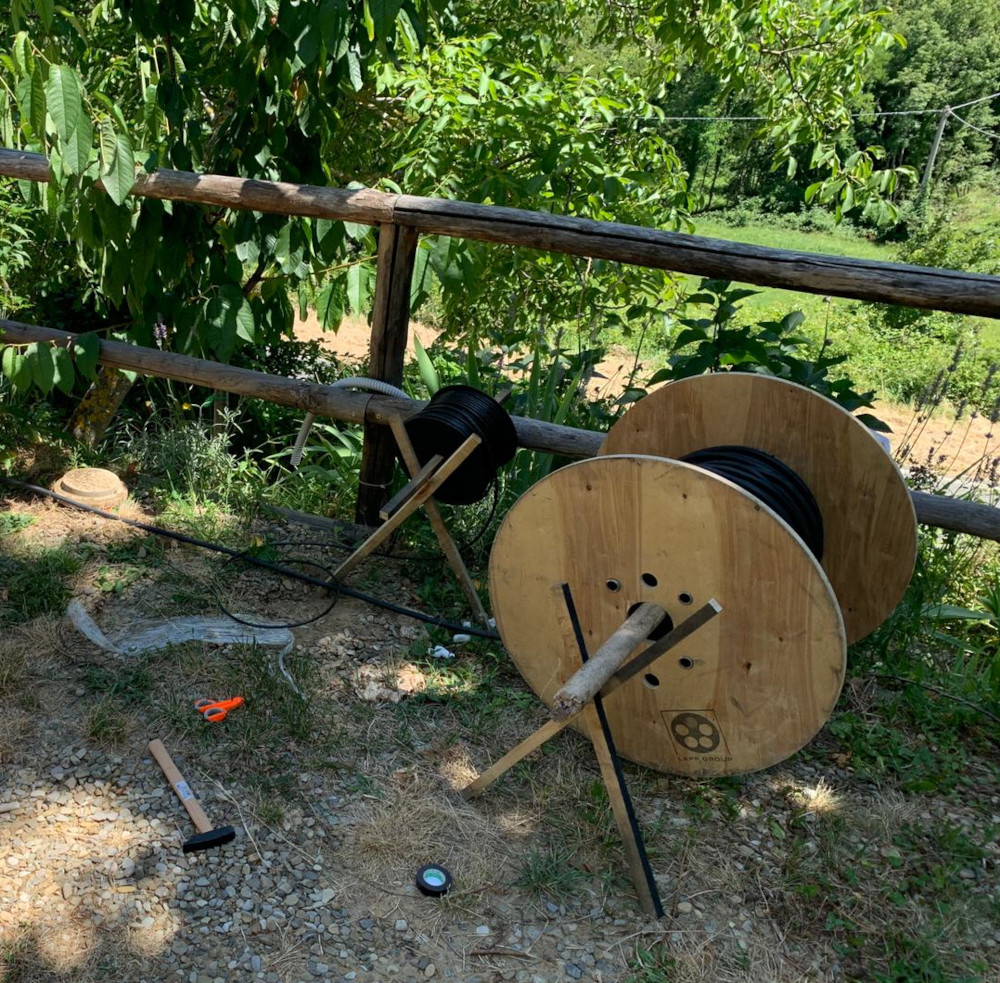
Power and ethernet
Bringing power and ethernet from the house to the place was no easy task: 100m of thick 4mm² power cable were necessary, plus a shielded CAT6 ethernet cable. The wires had to go though a wall, under a pathway, above some threes up to the field. Since it was an old countryside house, we even had to upgrade the electrical cabinet and ask an ISP for wireless internet (with a receiver dish on top of the house)! If it weren’t enough, the ethernet cable turned out to be unable to transfer data over such a distance, so we had to add a PoE (power-over-ethernet) rang extender in the middle of the cable.
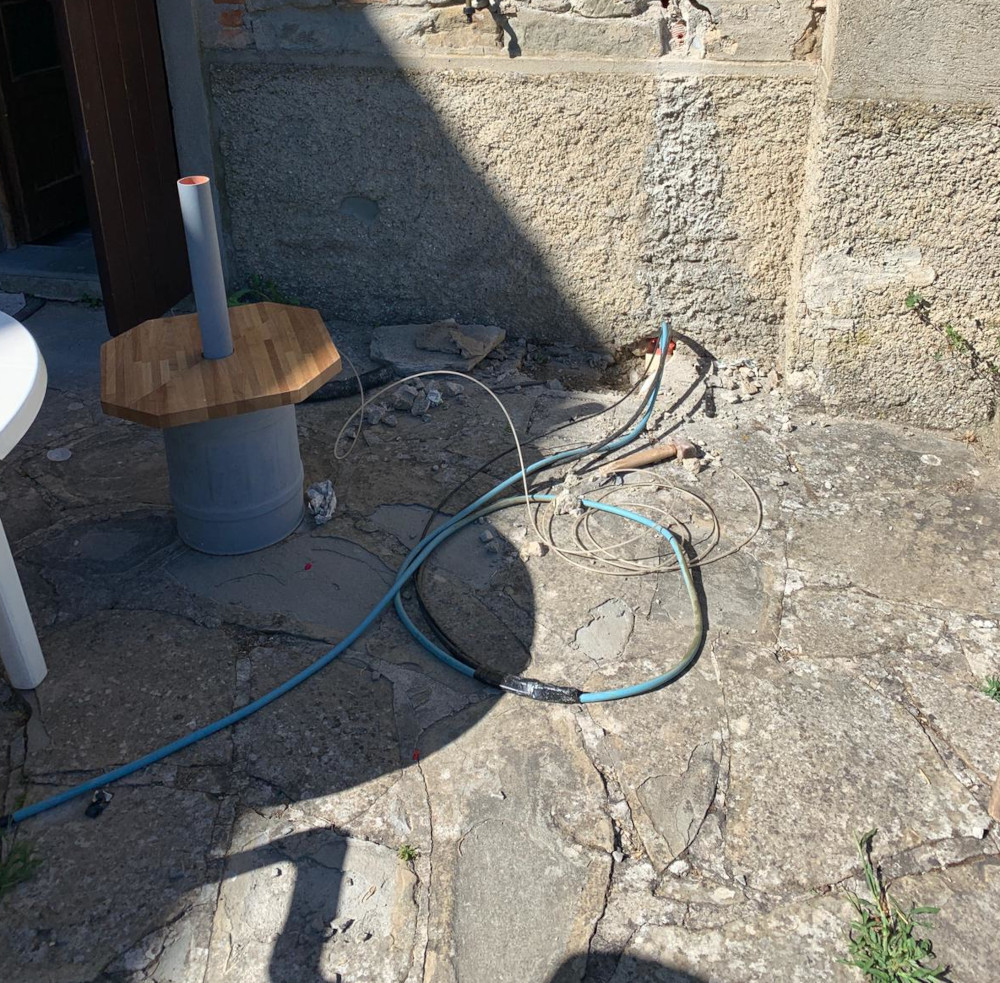

Other important factors that needed consideration were the grounding of the new electrical system and the ethernet surge protection, just in case a lightning or other disruptive event occurs.
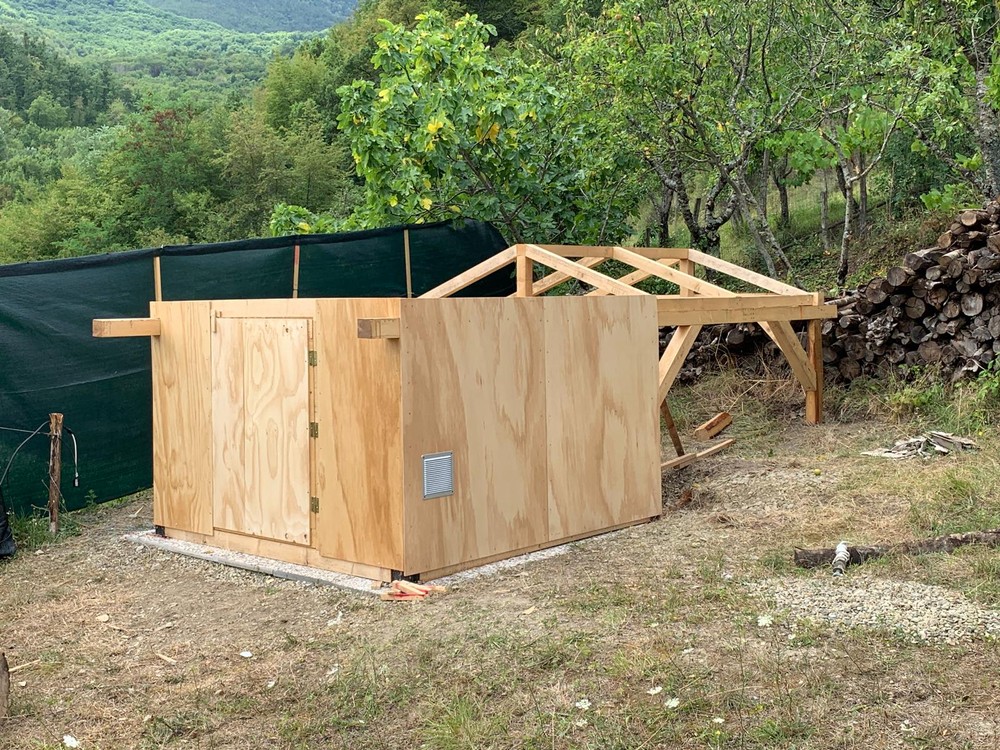
The structure
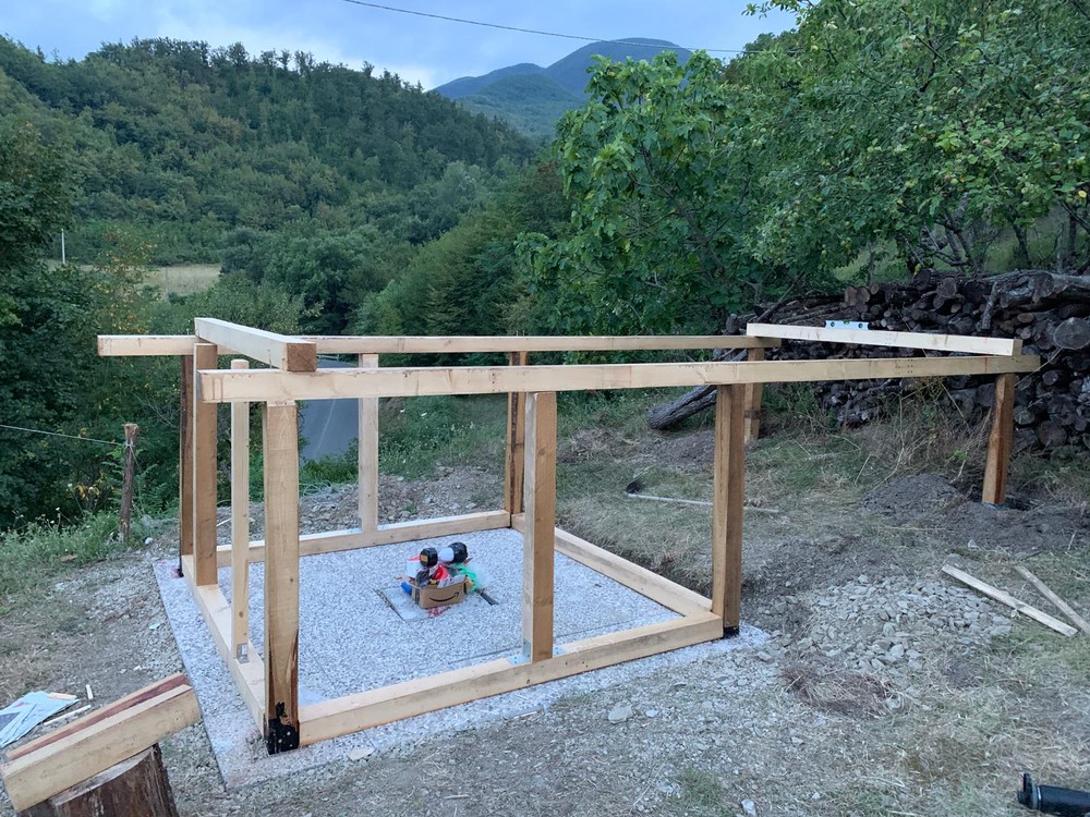
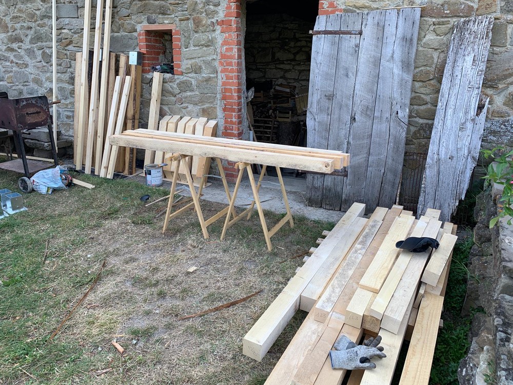
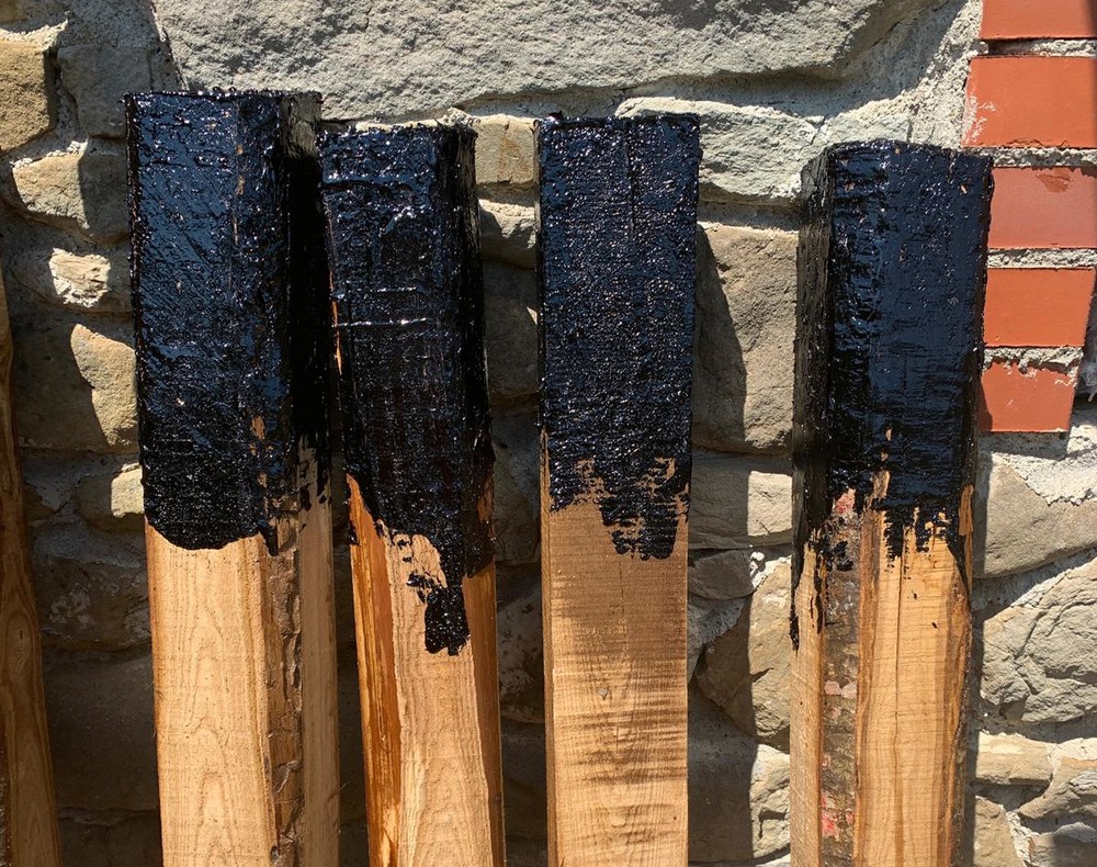
The observatory’s structure is composed of several fir wood panels and beams, except for the six main vertical carrier beams, which are made of local chestnut wood. This is very important because those are the only parts of the structure in direct contact with the ground and chestnut wood is resistant to rain and rotting. Panels and beams were sourced from local sawmills and carpentries and then refined by my friend.
Almost 20kg of high protective impregnating agent were used to paint all the parts, and a layer of melted tar was applied on the tips of the carrier beams to further protect them when they are buried into the ground.
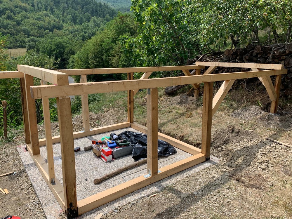
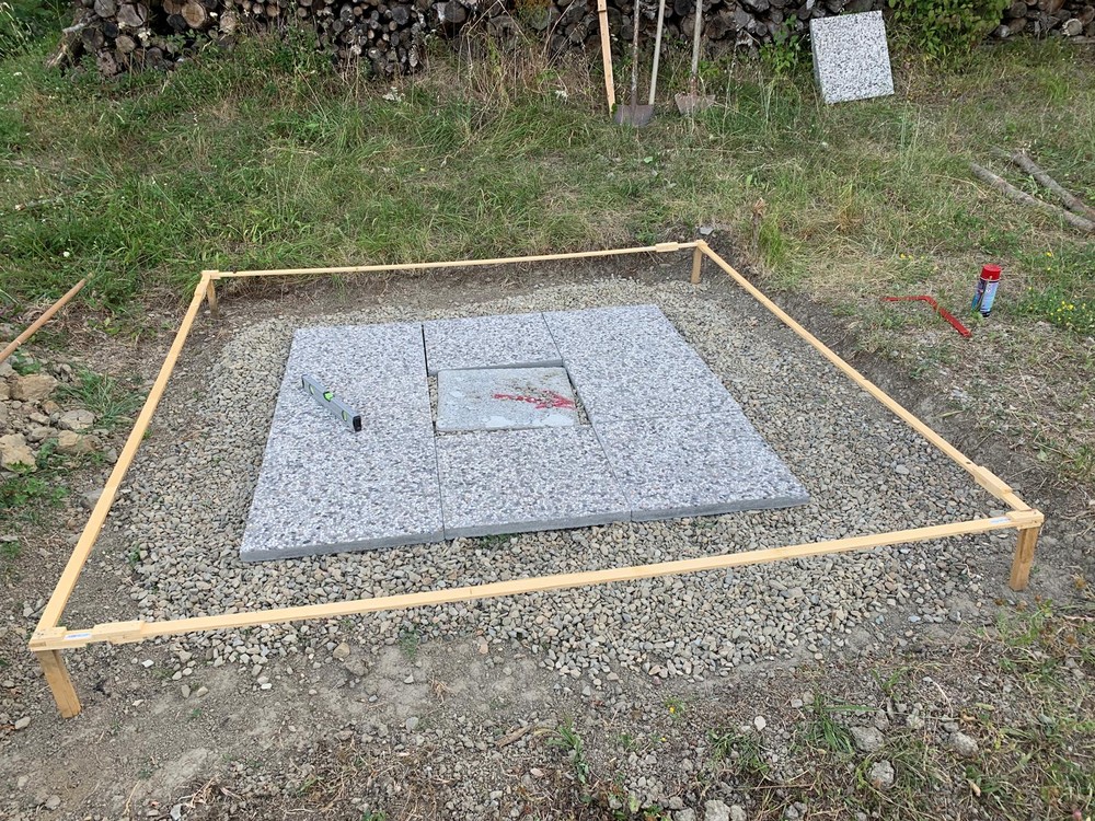
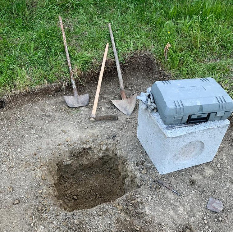
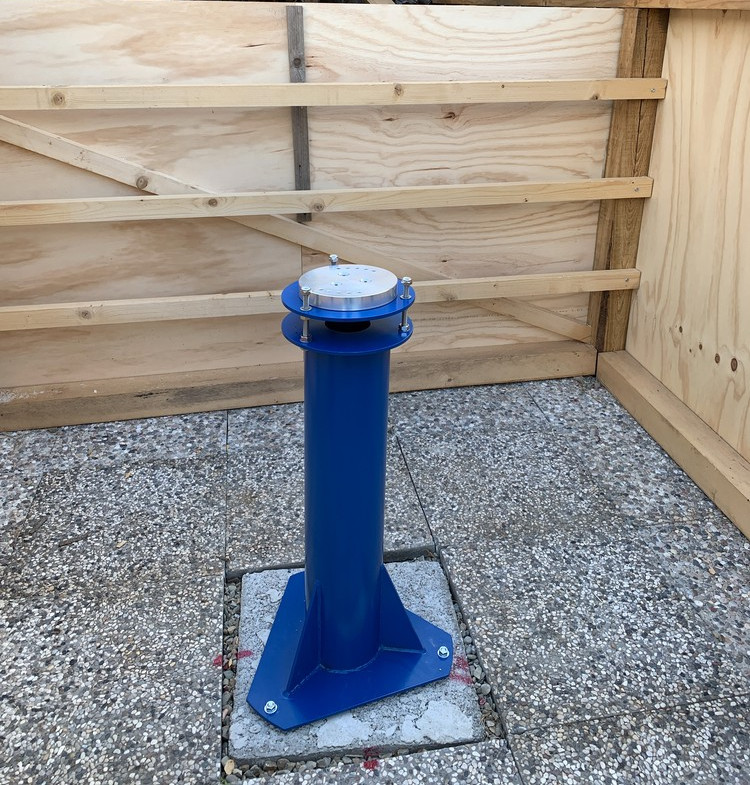
The first construction phase included the ground leveling and the installation of the base for the telescope column (a prefabricated 50x50cm concrete cockpit was used for this purpose). All the works were done manually with hoe and shovel and the aid of a demolition hammer for the concrete cockpit trench and main vertical carrier beams pits. Below the first layer of grass and dirt, the ground was composed of relatively compact marl and siltstone, which is good for the overall stability of the structure. Some cement was also poured around the concrete cockpit to further improve the stiffness and stability of the telescope base.
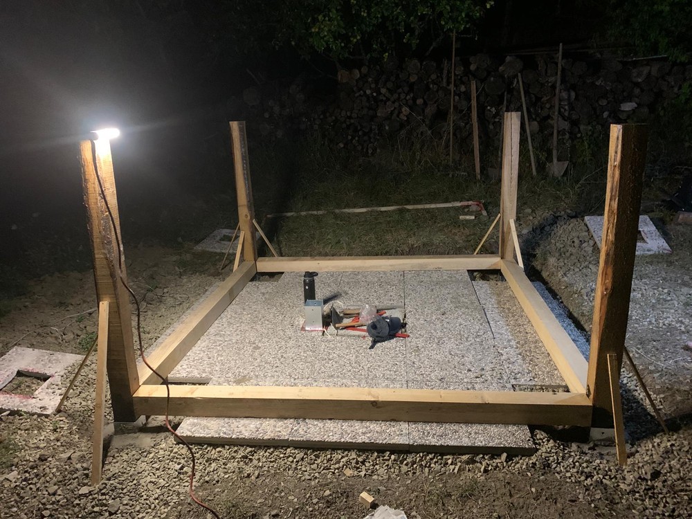
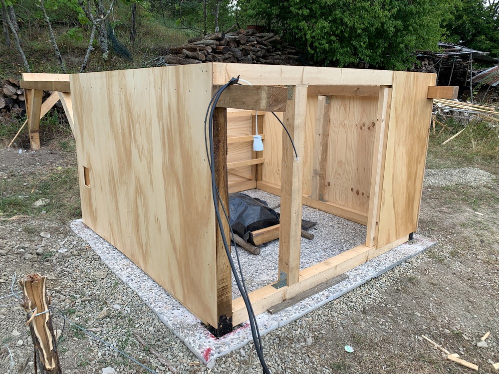
The six main chestnut wood carrier beams were fixed into the ground, while the rest of the structure leans over concrete outdoor floor tiles placed on a leveled gravel bed (also helping with water drainage).
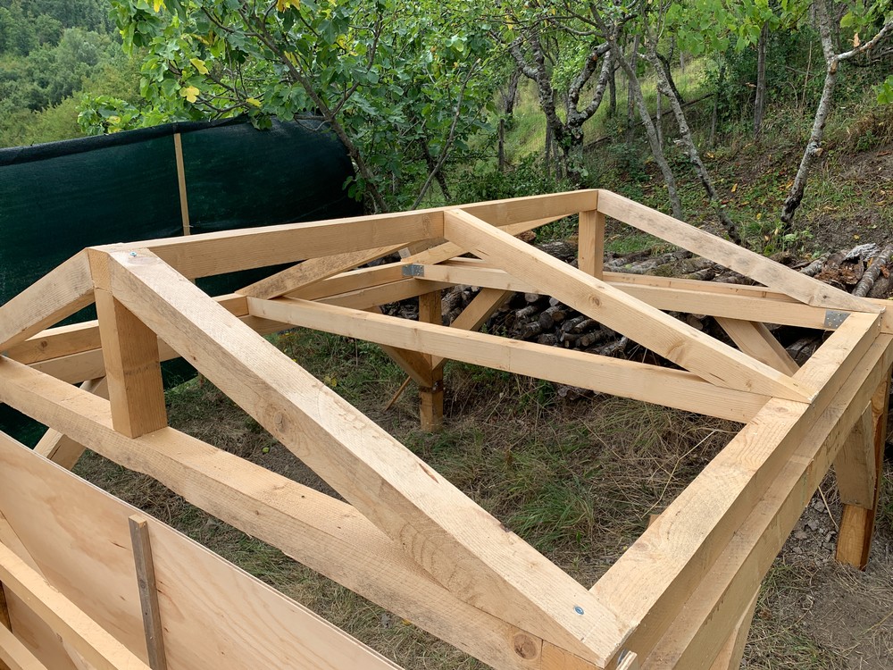
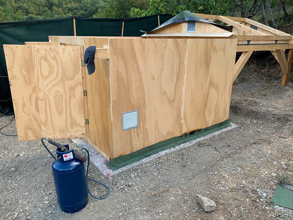
The rest of the carpentry works involved fixing the whole structure together, including the long 5m horizontal beams that serve as a base for the rails of the roll-off roof. Bituminous membrane was applied to further protect the base of the structure and the front canopy.
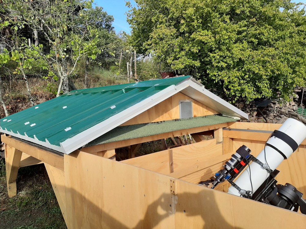
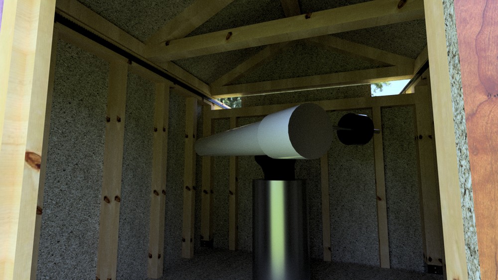
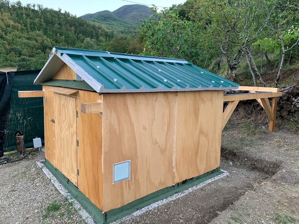
The roof
The roof was assembled directly in-place due to its size and weight. It slides on the rails thanks to four v-groove gate wheels. Then, two insulating metal panels were bolted on top of the wooden structure. Such panels were chosen for their relative lightness, high stiffness and good thermal insulation properties.
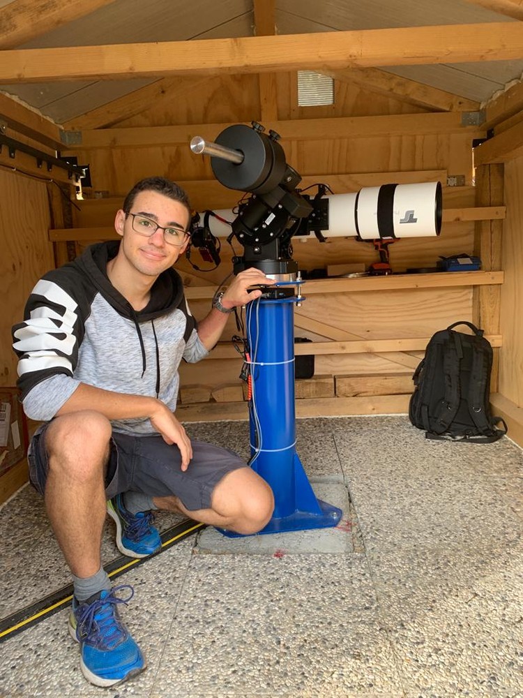
All the works were done late in the day and even at night to escape the intense heat of the summer season! Finally, the telescope column was bolted to the concrete cockpit base.
Server and electronics
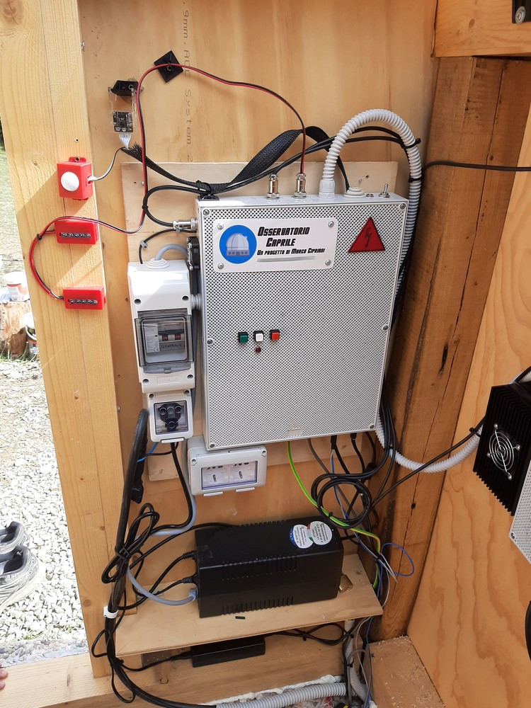
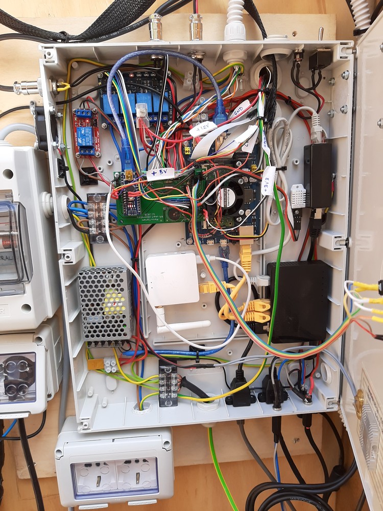
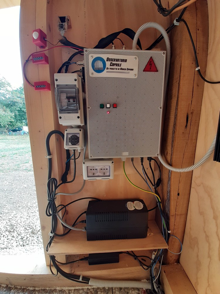
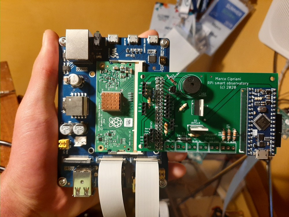
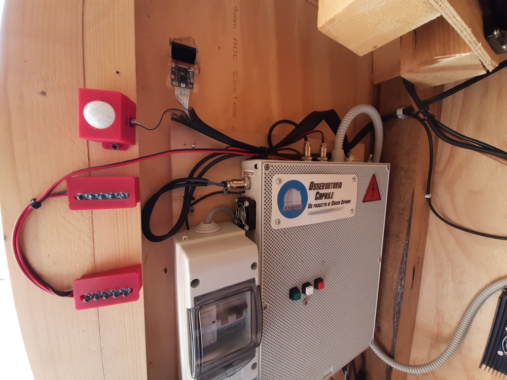
The server of observatory is in charge of serving a web interface for remote management. It runs on a Raspberry Pi Compute Module 3, equivalent to a Pi 3B+ but with two camera inputs (one for the security camera and one for the all-sky). The board is then connected to an Arduino Nano and a custom-made PCB which allow the server to control relays, check the sensors and move the roof’s stepper motor. Inside the electronics there is also a Gigabit network switch with surge protector, a Wi-Fi AP, the server power supply and all the power management system (consisting of several relays, MOSFETs and derivations for both the 12V and 220V lines). Surrounding the main box, an IR camera, switchable IR LEDs (to avoid disturbing the telescope’s CCD) and a PIR sensor were added.
Huge thanks to DigitSpace for providing most of the electronics used in this project: they were so kind to send me Arduino sensors, spare electronics parts and a Raspberry Pi camera to complete the server box. Here’s the list of components we’ve used:
Plus, power plugs, boxes and a lot of meters of electrical wires were necessary! Photos of the completed server:
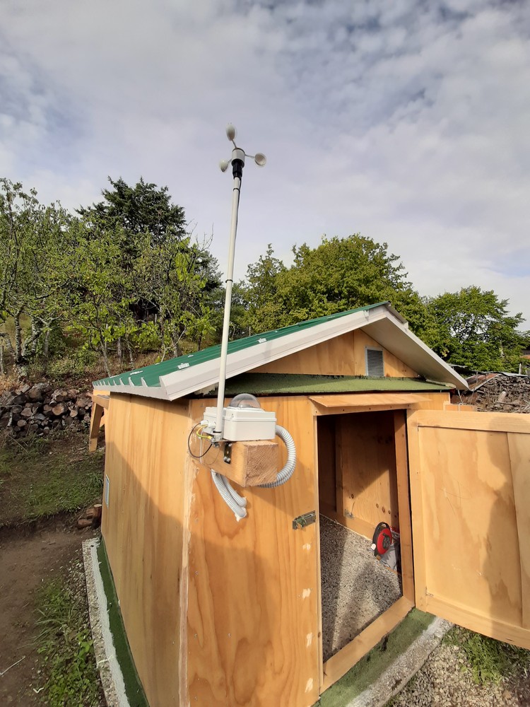
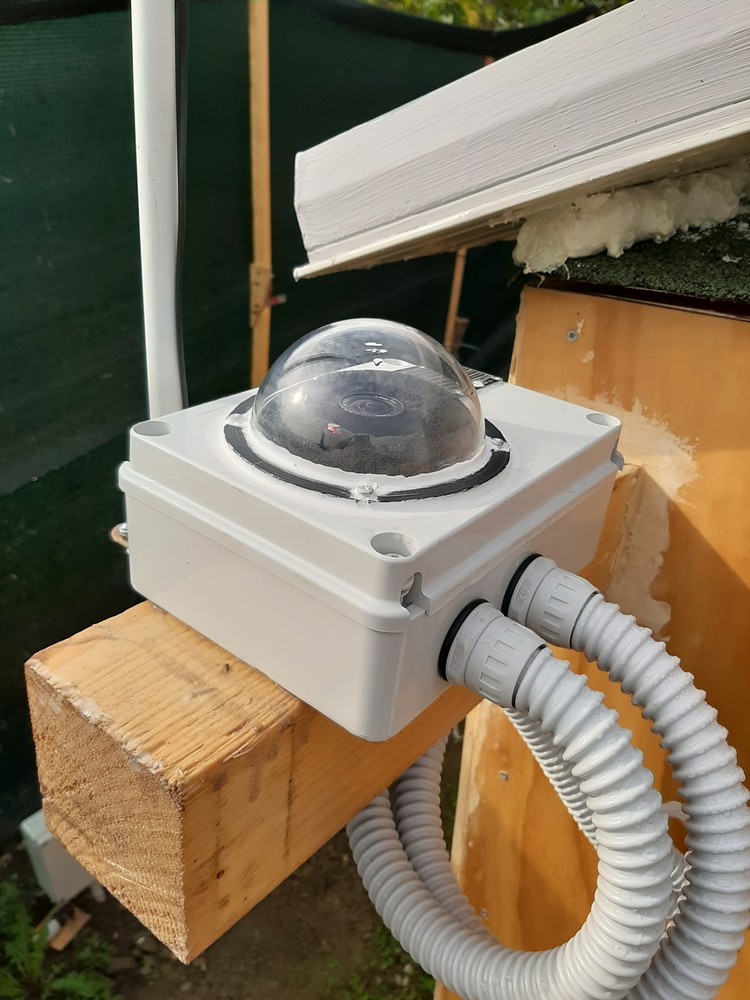
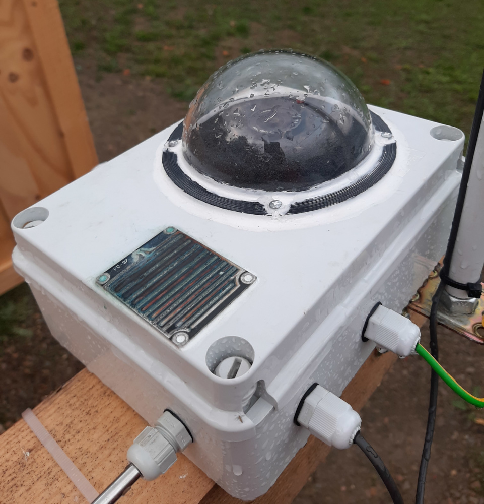
Weather station
The observatory’s weather station has several sensors which can report rain, external temperature, light and wind speed. Plus, there is an all-sky fisheye camera used to check for cloud coverage. The box of weather station was made starting from an IP65 electronic enclosure and a plexiglass dome, sealed with silicon. Then, I used cable glands and corrugated pipes to route the wires from the station to the server, where everything is connected. A Raspberry Pi High-Quality camera with a 2.5mm fisheye lens was used for the all-sky camera, held in place by some 3D printed parts and later covered by a piece of foam sheet; the light sensor was mounted near the camera inside the dome and it was used to switch between night and day modes for the cameras. Adhesive 12V heaters were added around the dome (internally) and beneath the rain sensor to get rid of the dew. The anemometer was mounted on a grounded iron rod and then connected to the weather station.
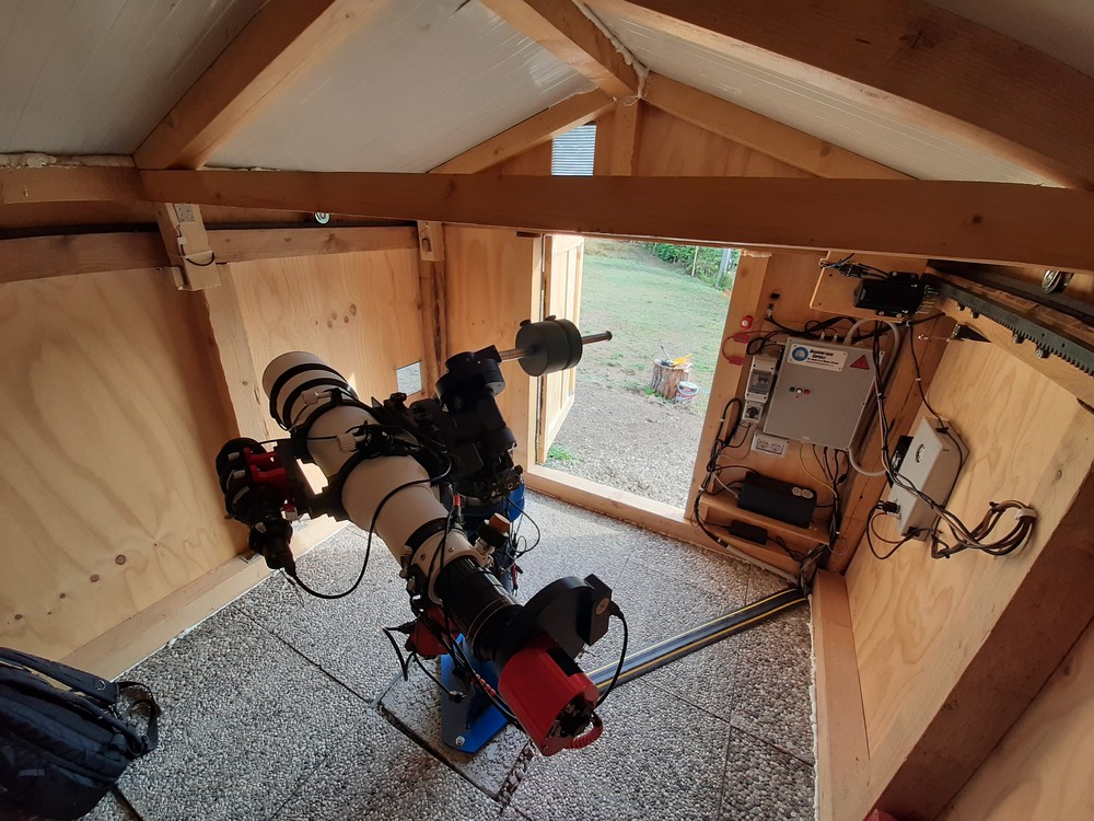
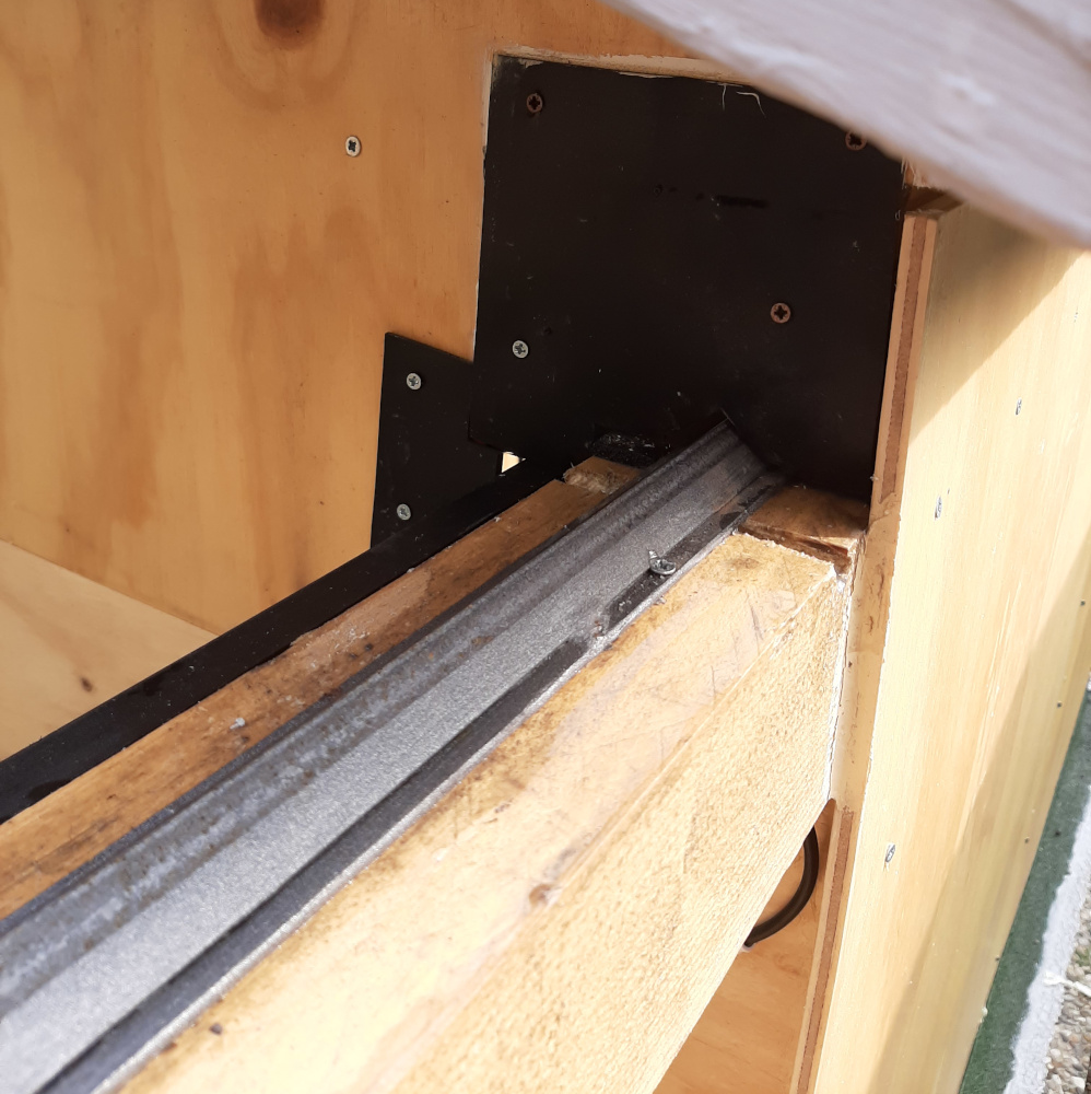
The motor and the sliding system
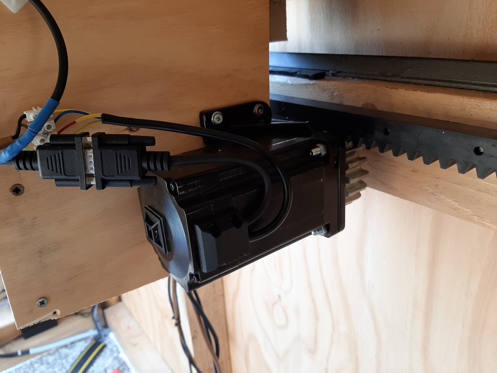
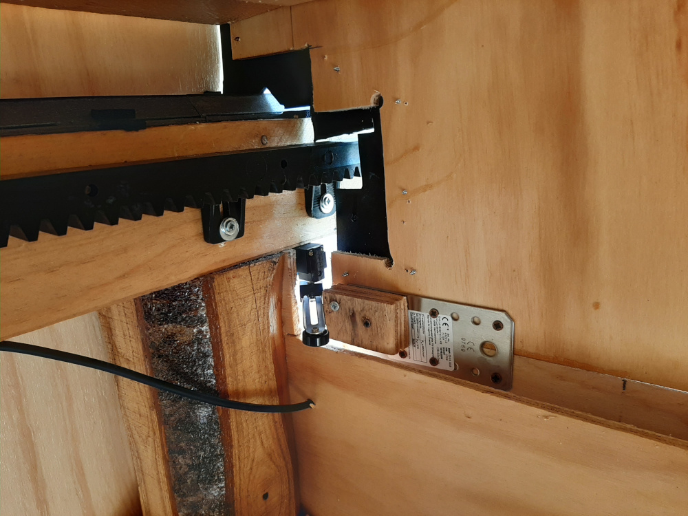
The roll-off roof slides thanks to two house gate rails and four v-groove gate wheels. It is moved by a huge NEMA 34 closed-loop stepper motor capable of providing up to 9Nm of torque. This enormous amount of force helps the roof overcome friction, the small misalignment of both the rails and the rack and wind, as the observatory must be able to close even in emergency situations. One month after the completion of the observatory, indeed, while the roof was open and the telescope was in use, a sudden 50Kph wind started blowing, and the motor was capable of closing everything in less than two minutes. The motor’s encoder ensures that the stepper never loses steps, which may lead to a partially open or closed observatory.
The motor was mounted on the roof, which means that it moves while the rack stands still. While it is an unusual configuration, it was the only solution to the constrains of the observatory. As an advantage, however, this system allowed us to put the motor and the pinion below the rack, which means that strong wind cannot lift the roof (at least without breaking the motor or its support). The other side of the roof is locked by electromagnetic locks, which block both manual sliding and roof lifting when engaged.
Two endstops, one at the beginning and one at the end of the track, help the software double-check if the roof is closed and eventually correct with extra steps. Thanks to these stops, the software can also automatically park the roof when it doesn’t know the current position or operate the roof after a power loss. Moreover, the motor is powered by a 48V 8A power supply and a closed-loop stepper driver, connected to the Arduino which sends the signals. Overall, the roof takes up to two minutes to close or open.
A very difficult part was getting the right stepper driver and power supply for the job. After two months of runtime, the 8A power supply broke down and needed to be replaced by a good, heavy toroidal transformer (some stepper drivers accept both DC and AC inputs). Unfortunately, the first stepper driver had bad luck and burnt too, probably because of excessive peak load or because of the switching power supply. It was replaced by a more expensive StepperOnline driver with a higher current rating. Because of all these dead electronics parts, we decided to replace the UPS of the observatory with a bigger pure sine-wave UPS, more suited for peak loads, toroidal transformers and sensitive devices. Note: these new parts are not shown in the photos.
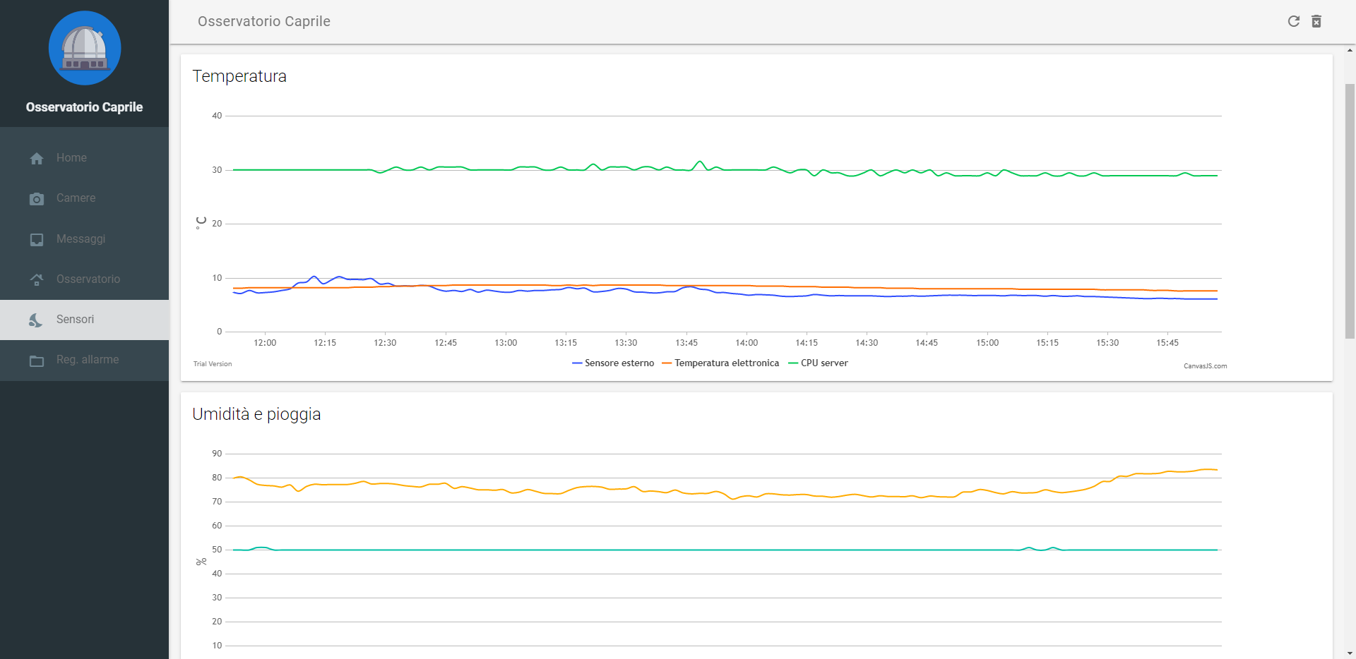
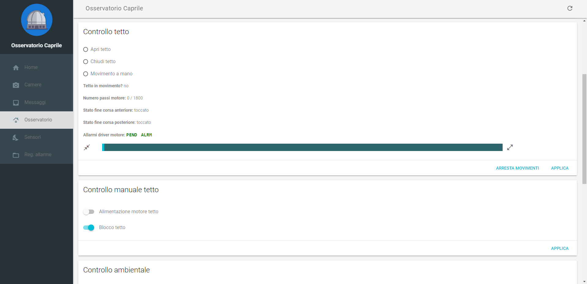
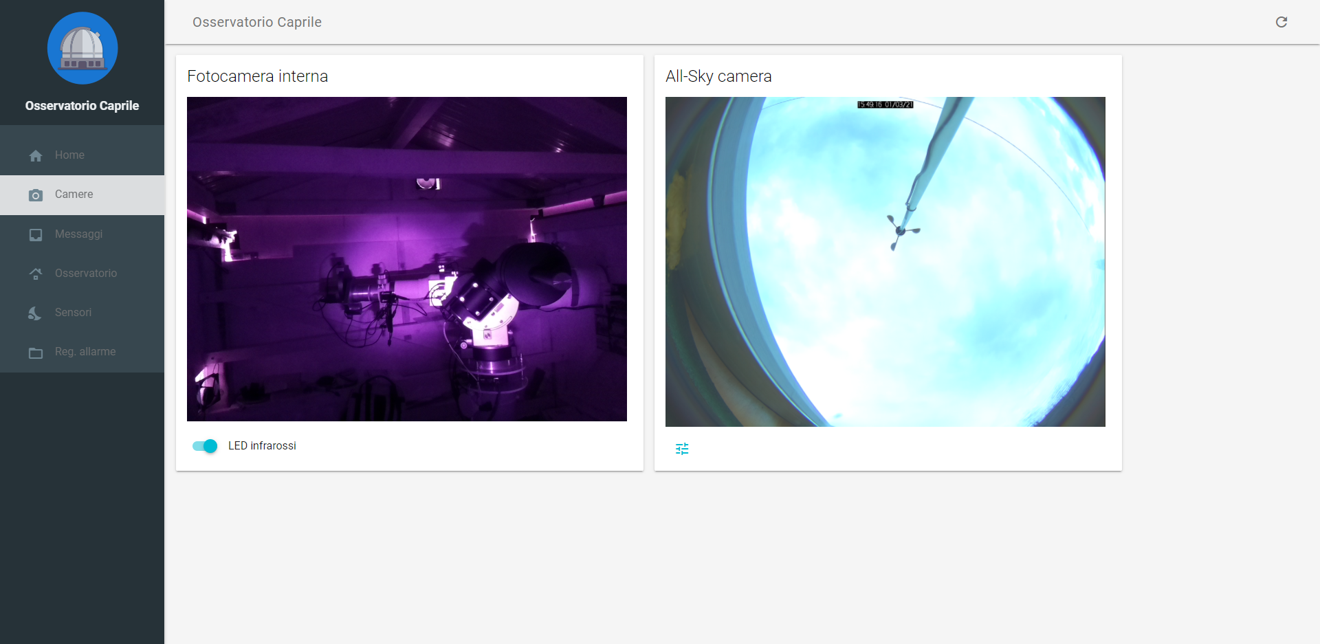
Web interface
The web interface can be viewed from any browser, which makes it extremely convenient and easy to use. It provides the following functionalities:
- Shows the cameras in real time
- Displays the history of every sensor in the past four hours
- Can turn on and off every device and power plug
- Opens and closes the roof, shows the curren position and the status of the endstops
- Sends wake signals to the telescope’s computer
- Records using the security camera if a movement is detected via the PIR sensor
- Controls the weather station’s heaters
- Logs and displays all the errors that occur
Here are some screenshots (the UI is in Italian, sorry):
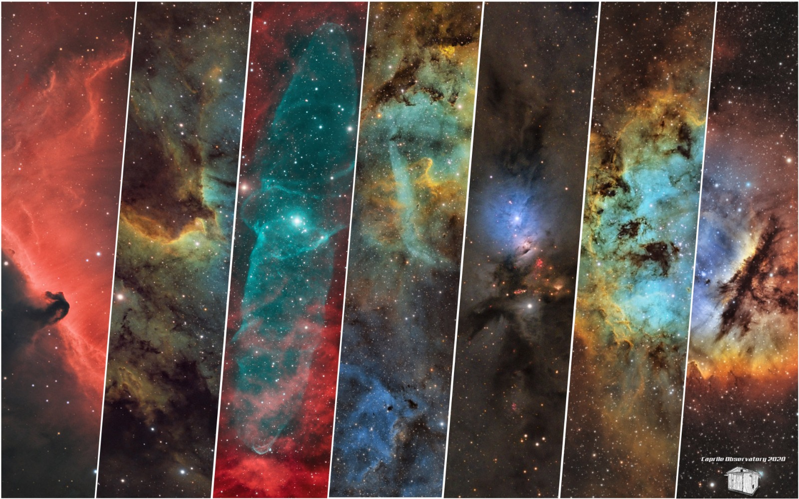
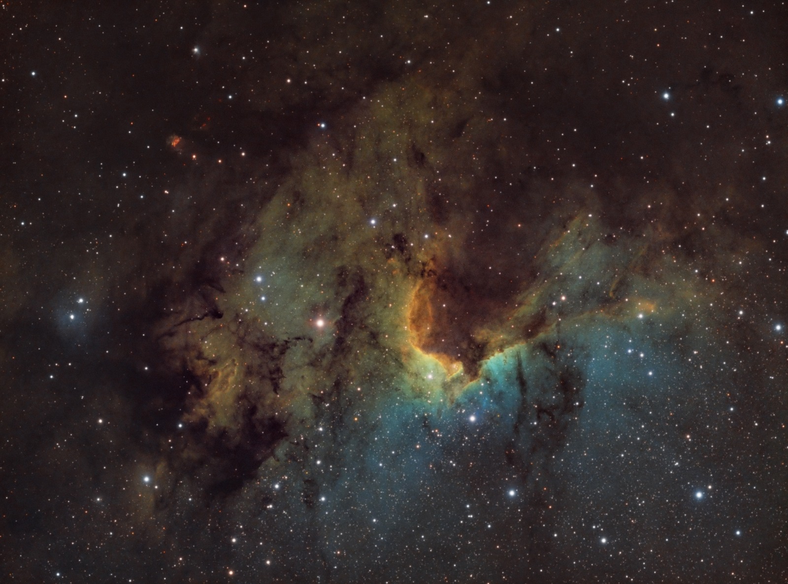
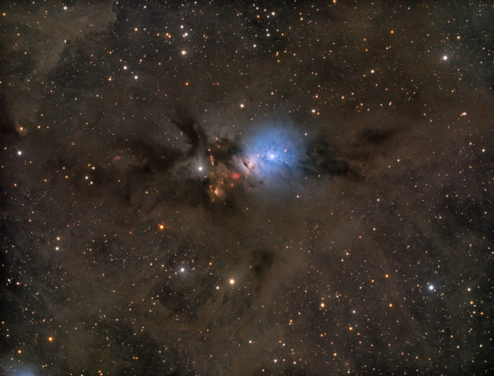
The results!
These are some of the astro-photos taken from the Caprile Observatory, remotely controlled from Florence: