Making it yourself
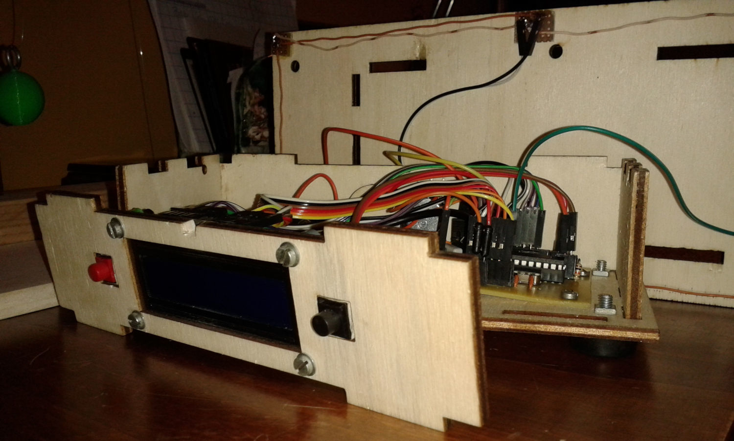
The laser cut box
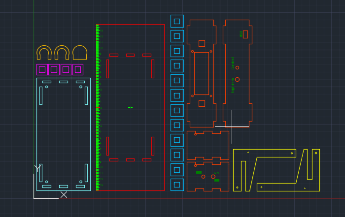
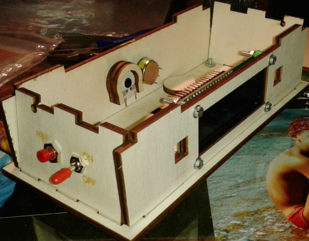
Cut this structure from plywood (4 mm thick) with a laser cut machine, then asseble it, put the components on the panels and fix them with some nails and vinilic glue. Download DXF/DWG files at the bottom of this page (designed with AutoCAD 2016).
The structure
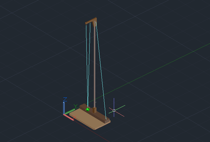
If you haven’t got a pendulum, you can make one yourself starting from this example (it’s an exact copy of the one I made). A 27,5·16·1 cm piece of plywood, a 5·27,5·2 cm splint and a rod are enough. Then use rings, fishing wire and a ball to complete the pendulum.
The mass
I hadn’t got an iron mass (would be better, of course), so I made a ball with a 3D printer and I added a ring to hang it to the wire. The heavier and thinner it is (see pendulum clocks: the mass is flat to avoid friction with air), the longer it will oscillate.
The PCB
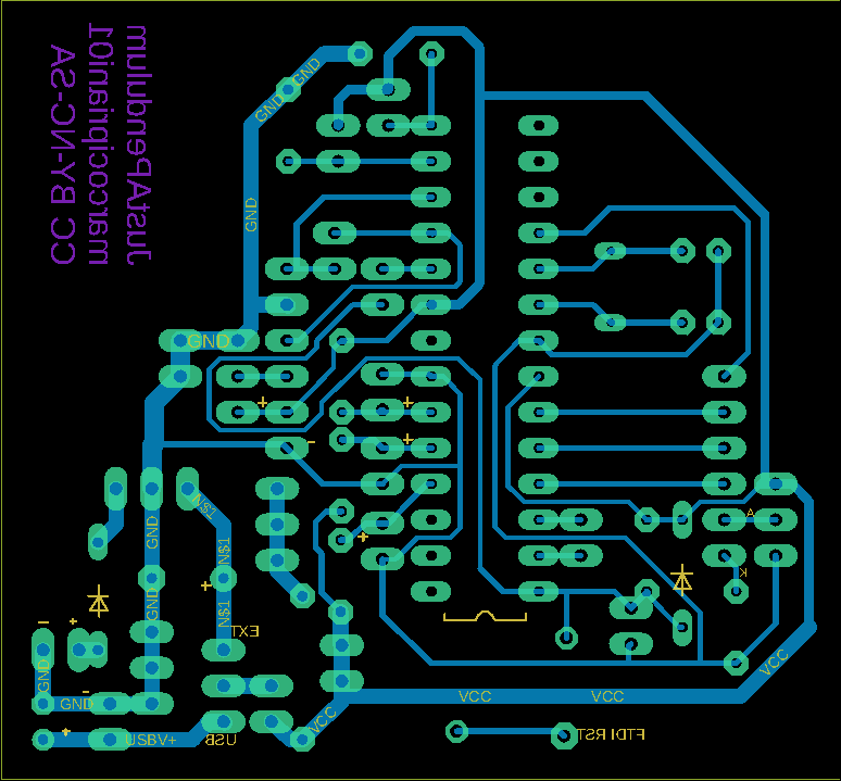
This is the less expensive method to create a homemade PCB using only low-cost stuff:
- Laser printer (600 dpi or better)
- Photo paper
- Blank circuit board
- Muriatic acid (>10% HCl)
- Hydrogen peroxide (10% solution)
- Clothes iron
- Acetone
- Steel wool
- Safety goggles and gloves
- Sodium bicarbonate
- Vinegar
- Paper towel
The first step is cleaning the blank PCB with steel wool and water. If the copper appears a bit oxidized, you should wash it with vinegar before. Then, scrub the copper side with a paper towel soaked in acetone to remove any remaining dirt. Accurately rub every part of the board. Do not touch the copper with hands!
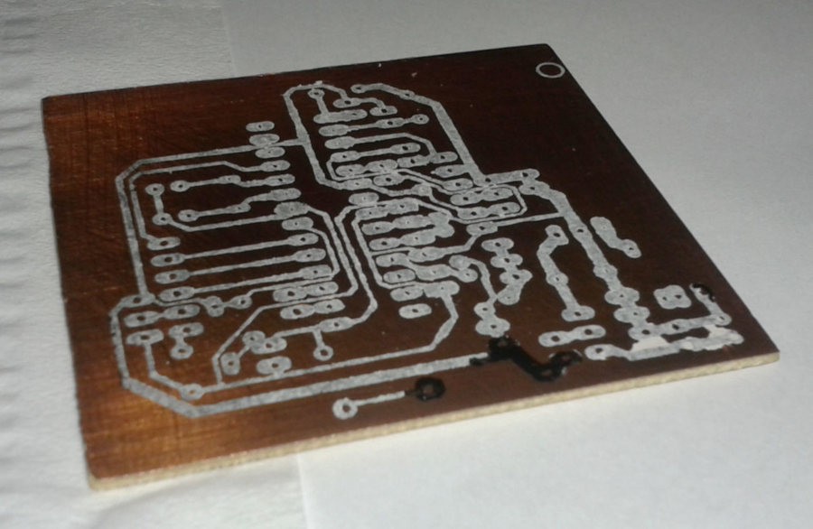
Print the PCB.pdf file at the bottom of this page using a laser printer and do not touch it with fingers. Cut it, align the image on the copper side and press it with the clothes iron (it must be hot but without vapour) for about five minutes. Let it cool with all the paper, then remove the paper very slowly and carefully under water. If there’s no toner on the copper, repeat the procedure; Use a small permanent marker to fix some missing connections.
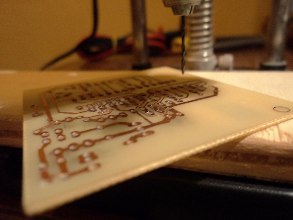
Now it’s time to use acid to etch the PCB. In a plastic box put three glasses of muriatic acid and one of hydrogen peroxide; you can also try with equal amounts for a more powerful etching. Put the PCB in the solution (pay attention to your hands and eyes) and wait about ten minutes. When the etching is finished remove the board from the solution and wash under water. Put two spoons of sodium bicarbonate in the acid to neutralize the solution and throw it in the WC (or take it to a waste collection centre).
Electronics
Here’s the schematic:
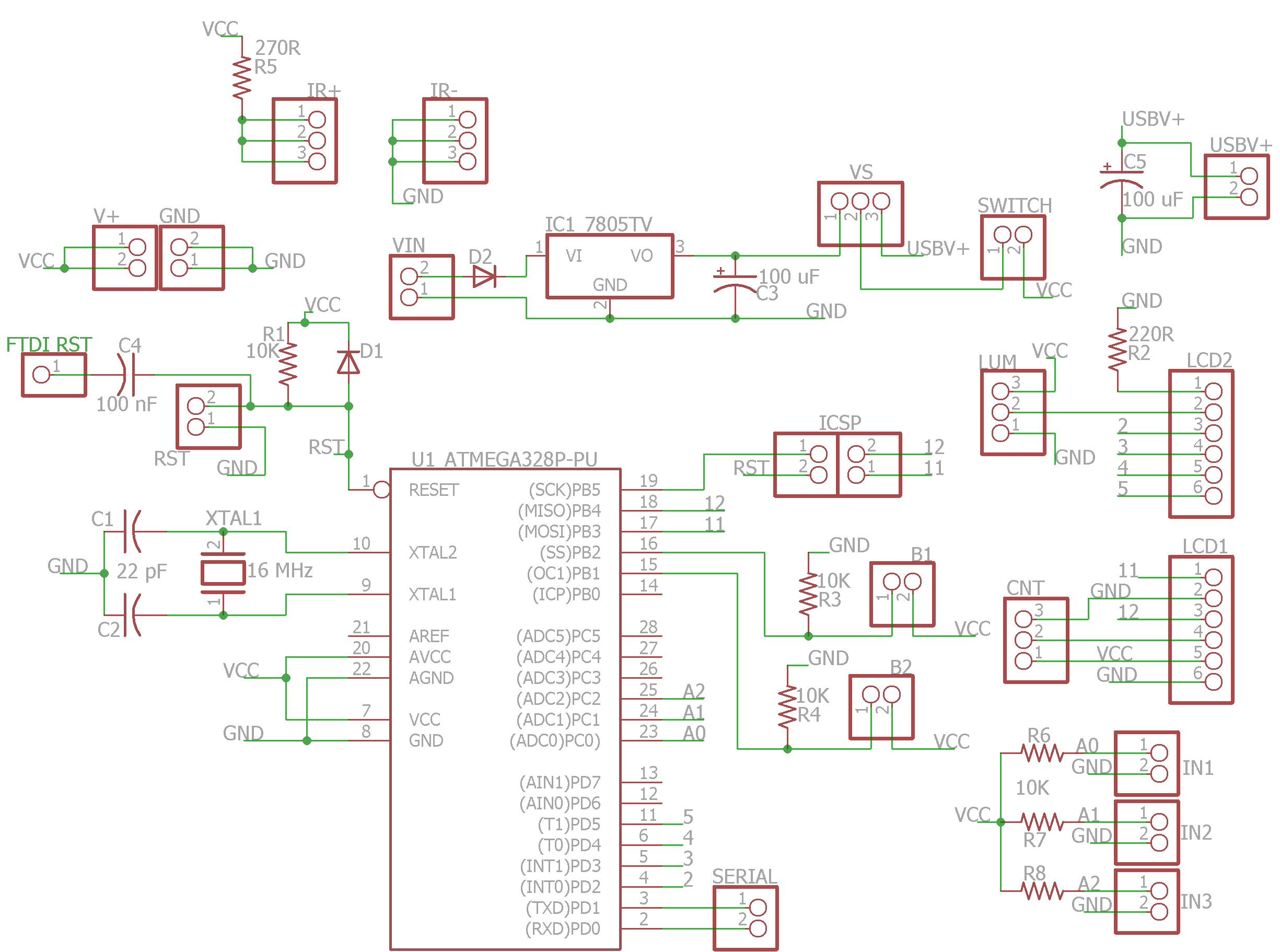
Parts needed:
- ATMEGA328P MCU
- 2x 22 pF capacitors
- 3x 100 uF capacitors
- 2x 1N4148 diodes
- 7805TV voltage regulator
- 6x 10K resistors
- 2x 220R resistors
- 16 MHz crystal oscillator
- Pinheads
- USB-to-serial adapter
- 940nm side-looking infrared emitters and IR detectors (I bought these from Sparkfun)
- 9V battery and battery holder
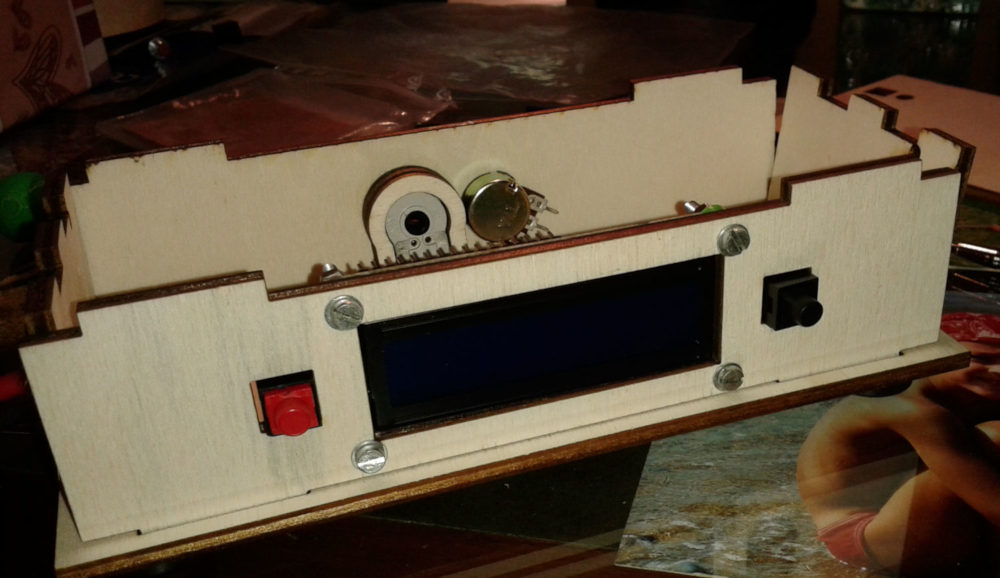
- 16x2 LCD screen
- 2 buttons
- A potentiometer and a trimmer
- Wires, wires and wires
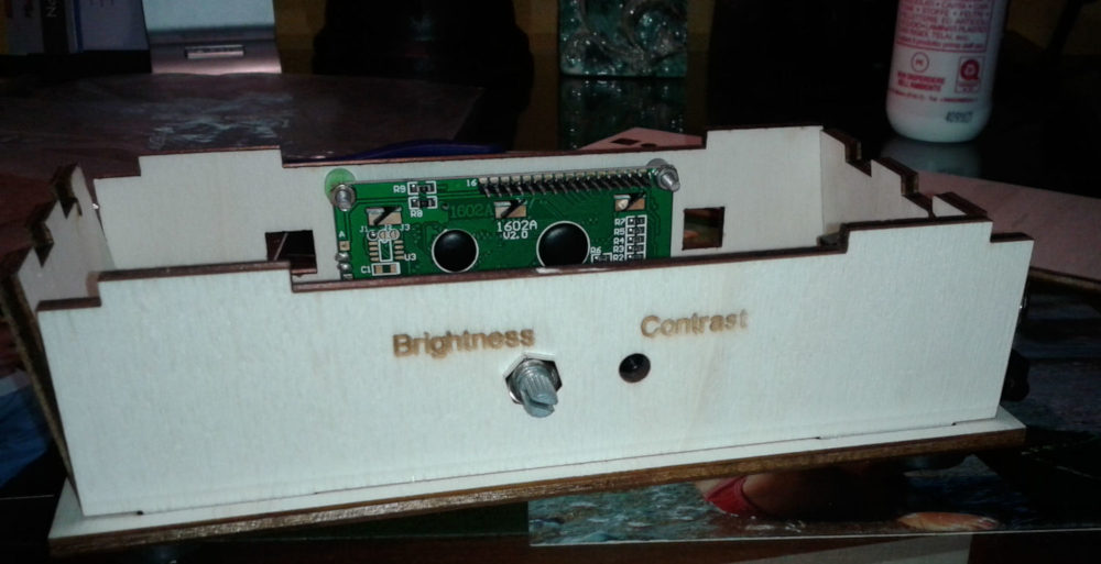
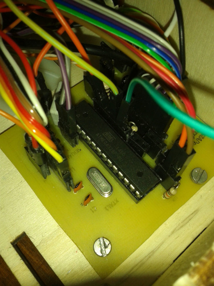
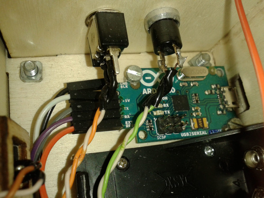
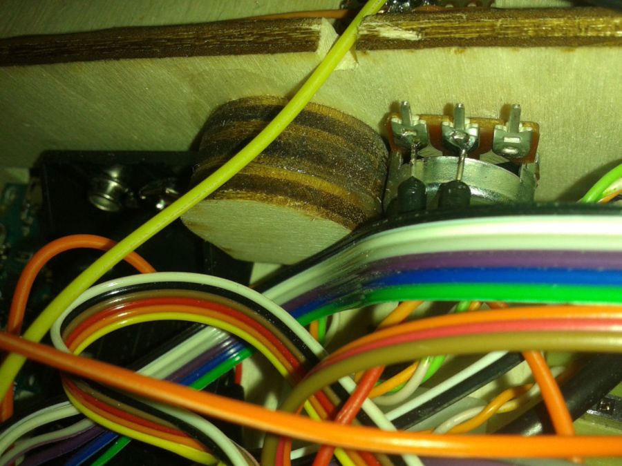
Now that you’ve bought and collected the components, pick a solderer and solder them all! Then fix the PCB in the box, connect all the wires to the LCD, the USB-to-serial adapter, the potentiometer and the trimmer (for display brightness and contrast). Refer to the schematic, the PCB model in the previous step and to Eagle CAD files at the bottom of this page to correctly place all the parts and wires.
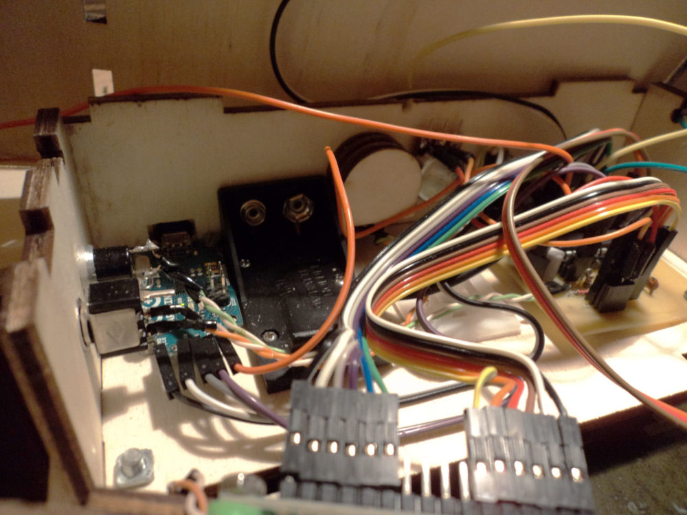
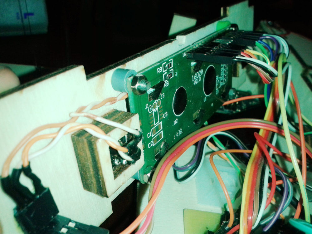
Sensors
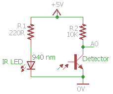
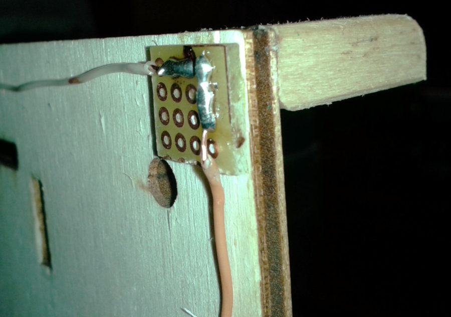
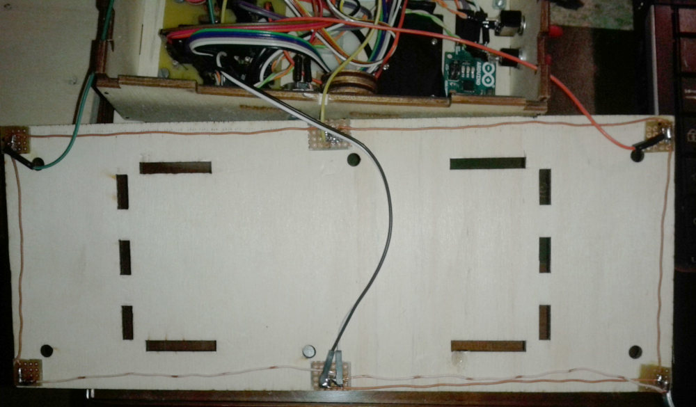
Add the sensors as shown in the pictures, then make some caps (I used a rotary tool to engrave them from a wood splint) to cover and protect them. Then connect them to the main board.
Downloads
Companion source code - Visual Studio 2015
Schematic, Autodesk Eagle 9.2.2
You’re ready!
Go back and start using it!

This work is licensed under a Creative Commons Attribution-NonCommercial-ShareAlike 4.0 International License.